Beams in Joint to Shells
Scripts on this page are available here:
beams_in_joint_to_surface_model.js
This example shows how to convert pipe beams in a joint to shells
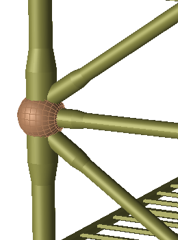
The utility script will convert the pipe beams to shells
To generate the above scenario:
Create a new GeniE workspace, read in the file B10_clean.js. This is the same file that’s included in the B10 example of your GeniE installation.
Read in the file beams_in_joint_to_shells.js. This is the file which contains the function we will use to convert the pipe beams to shells.
In the GeniE command line, type:
paramDistanceToDivisionFromJoint = 0.5;
This is a variable used by the script to set at which distance from the joint the beams should be divided in order to create a shell model of the beams closest to the joint. The number 0.5 means that the beams will be divided halfway between the joint and the beam end or closest joint. See the explanation included at the top of the .js file for a more thorough explanation. In the GeniE command line, type:
ConvertPipeBeamsInJoint(Jt1);
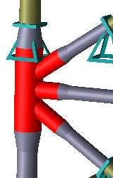
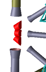
Explode the plates and delete the internal plates that was created when converting the joint,
as seen below. The plates shown in the illustration to the right should be deleted.
Create a new mesh property, set 0.1 m to element length and apply the new mesh setting to
the pipe shaped shells.
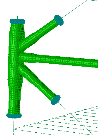
Run analysis. Inspect the model in mesh view, it should look as shown in the image to the
right on the top of this page.